معلومات ذات صله

استشر الولايات المتحدة
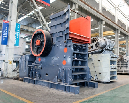
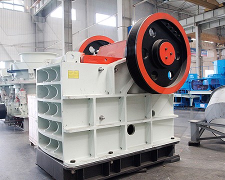
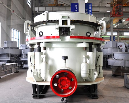
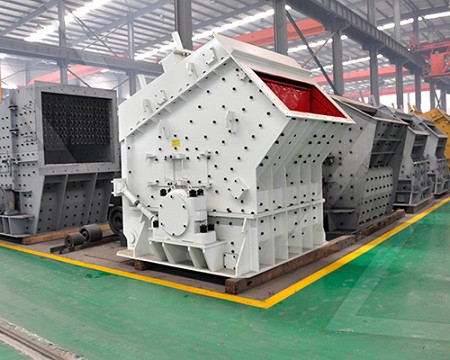
بصفتنا مصنعًا عالميًا رائدًا لمعدات التكسير والطحن ، فإننا نقدم حلولًا متطورة وعقلانية لأي متطلبات لتقليل الحجم ، بما في ذلك إنتاج المحاجر والركام والطحن ومحطة تكسير الحجارة الكاملة. نقوم أيضًا بتوريد الكسارات والمطاحن الفردية وكذلك قطع غيارها.


Magnetic circuit design (Chapter 4) Permanent Magnet Materials
2012年8月5日· Equations representing the magnetic circuit components are derived in this Chapter, and the elements they define are used in an equivalent circuit (similar in manyChapter information Abstract This chapter presents an introduction to the magnetic material properties useful for the design of electromagnetic devices The association ofThe magnetic circuit Book chapter IOPscience
Magnetic Circuit an overview | ScienceDirect Topics
The objective of magnetic circuit design is to determine the number of the coils, so that the magnetic induction density in the annular flow path generated by magnetic circuit isAbstract Magnetic circuit design has been traditionally difficult because of the usually nonanalytic nature of the solutions for fields emanating from arbitrary sources Further,Permanent Magnet Design: Methods of Magnetic Circuit
Magnetic Circuit Design for Power Electronics
2018年1月1日· Magnetic Circuit Design for Power Electronics ScienceDirect Power Electronics Handbook (Fourth Edition) 2018, Pages 571589 17 Magnetic CircuitPower Magnetic Devices Discover a cuttingedge discussion of the design process for power magnetic devices In the newly revised second edition of Power MagneticPower Magnetic Devices: A MultiObjective Design Approach, 2nd
Magnetic Circuit Design for Power Electronics ScienceDirect
Abstract The evolution of power electronics since the middle of the 20th century has been largely dependent on the introduction of semiconductor devices The invention of2023年7月26日· Optimization of magnetic components design, such as power inductors and transformers, is most needed to improve the performance of future powerA DataDriven Inductor Modeling Technique Using Parametric
A new design of magnetic circuits in magnetorheological
2020年12月10日· In this work, MR damper of the final design (Design C) is manufactured, and experiments are conducted to demonstrate some advantages of the proposed new design concept of magnetic circuit structure After investigating the effect of the piston stroke length on the damping force, a comparison of the magnetic analysis between2014年9月16日· 3 • In the magnetic circuit of Fig, the driving force, analogous to voltage, is called the magneto motive force (mmf), designated by F The magneto motive force is created by wrapping N turns of wire,Magnetic circuits | PPT SlideShare
Scaling of Magnetic Circuit for Magnetically Shielded Hall Effect
2023年3月5日· To speed up the design procedure of MSHETs, a simple methodology was developed focusing on thrusters with power levels lower than 5 kW It relies on the use of a database of MSHETs (power range 01–5 kW) built by scaling a known MS thruster As application, the magnetic circuit for a 2000 W MSHET has been designed2008年12月16日· The main dimensions of the basic types of electrical machines, equations for current linkage, magnetic voltage of air gap, and individual parts of the magnetic circuit are presented Carter factor, equivalent air gap, and core length are defined Current linkage for the threephase distributed 2 p pole winding and the required magnetizingDesign of Magnetic Circuits Wiley Online Library
What is Magnetic Circuit? – Definition & Explanation
2021年7月2日· An electric circuit is the path provided for electric current On similar lines, the magnetic circuit can be defined as the closed path traversed by the magnetic flux In the electrical circuit, various electrical quantities like current, emf and resistance can be easily calculated with the help of the simple Ohm’s lawCheck online our FAQ page and get answers related to Magnetic Theory and Design For any other information, call us at (847) 3801333 Newsletter Connect calculated by using values based purely on the geometrical parameters of the magnetic circuit, allows the magnetic design engineer to determine this operating point of the magnet on theMagnetic Theory and Design FAQ | Dexter Magnetic Technologies
Power Transformer Basics: The Magnetic Circuit
2020年7月10日· Transformers are static devices that transfer energy from one set of coils to another through a varying magnetic flux, provided that both sets are on a common magnetic circuit (core) A change in the magnitude of flux linkages with time induces electromotive forces (Figure 1) Figure 1 Elementary transformer, secondary open circuitedAbstract This chapter presents an introduction to the magnetic material properties useful for the design of electromagnetic devices The association of an electric circuit to the magnetic problem is the highlighted subject of this chapter This technique is a cornerstone of electromechanical energy conversionThe magnetic circuit Book chapter IOPscience
Magnetic Circuit Design and Multiphysics Analysis of a Novel MR
2014年1月1日· Magnetorheological fluid (MRF) is a kind of controllable or smart fluids whose rheological properties can be dramatically and reversibly varied by the application of an external magnetic field in milliseconds []Generally, MR fluid behaves like an ordinary Newtonian fluid, when exposed to a magnetic field, and the metal particles are guided2018年1月1日· Practically, in magnetic component design for power electronics, a linear relationship between B and H is assumed between their peak applied values (as shown in Fig 171) to enable definition of relative permeability based on the amplitude of applied magnetic flux density: (172) μ r = 1 μ 0 B ˆ H ˆ Examination of Fig 171 shows that dueMagnetic Circuit Design for Power Electronics ScienceDirect
Equivalent magnetic circuit method of estimating iron losses in
2022年6月9日· A magnetic circuit which passes through the center line between two adjacent or a pair of magnetic poles, is usually chosen as one for calculation, as illustrated in Fig 1Typical values of leakage factor are from 112 to 125 In the magnetic circuits, the magnetic leakage can be minimized by placing the exciting coils as close as possible to the points where the flux is to be utilized Fringing in Magnetic Circuit The magnetic lines of force repel each other while passing through a nonmagnetic materialSeries and Parallel Magnetic Circuits Your Electrical Guide
Design, modelling and analysis of a hybridmagnet variableflux
2022年8月1日· A hybridmagnet variableflux machine which has the variable seriesparallel magnetic circuit is investigated Magnetization state and magnetic circuit type of this variableflux PMSM are adjustable This machine’s equivalent magnetic circuit (EMC) model at different magnetization states is established and evaluated2014年9月1日· Thus, Iron Losses in Magnetic Circuit are: • Hysteresis losses • Eddy Current Losses The iron loss is the sum of these two losses Chapter 1 MAGNETIC CIRCUIT MAGNETIC CIRCUIT It is the path which is followed by magnetic flux It is basically ferromagnetic with coil wound around themChapter 1 MAGNETIC CIRCUIT SlideServe
Magnetic Circuits and Transformers IEEE Xplore
<P>This chapter contains basic concepts that can be used for all rotating machines and for power transformers It presents a more complete analysis and more detailed circuit models of reallife transformers When the transformer operates in sinusoidal steady state, the corresponding phasor circuit can be used to analyse it Threephase transformers canMagnetic circuit design has been traditionally difficult because of the usually nonanalytic nature of the solutions for fields emanating from arbitrary sources Further, unlike currents in electric circuits, magnetic fluxes are not neatly confined to wires but fill all of spacePermanent Magnet Design: Methods of Magnetic Circuit Design
Magnetic Circuit – Series and Parallel Magnetic Circuit
2021年7月26日· A magnetic circuit which has more one path for the magnetic flux is called as parallel magnetic circuit Consider a coil of N turns wound on limb AF carries an electric current of I amperes The magnetic flux φ1 set up by the coil divides at B into two paths viz − The magnetic φ2 φ 22017年1月7日· Magnetic Circuit Practically all electric power machinery (eg transformers, generators, motors) depend for their operation upon the magnetism produced by the magnetic circuits The closed path followed by magnetic flux is called a magnetic circuit (Fig 1) just as the closed path followed by current is called an electric circuitMagnetic Circuit Electronics Tutorials
Magnetic circuits | PPT SlideShare
2019年12月15日· MAGNETIC CIRCUITS (i) Simple Magnetic Circuit It consists of a closed iron ring wound with a magnetising coil as shown in fig The magnetic flux is produced by the coil Thus the coil acts as a source of mmf and the reluctance for the establishment of magnetic flux is offered by the iron ring2022年9月12日· Permanent magnet wallclimbing robots are widely used in the maintenance of tanks in the petrochemical industry and the overhaul of largepressure pipelines in the hydropower industry One of the difficulties is to achieve the safe and reliable adsorption of wallclimbing robots Based on the Halbach array, a doublelayerEnergies | Free FullText | A Novel Magnetic Circuit Design